
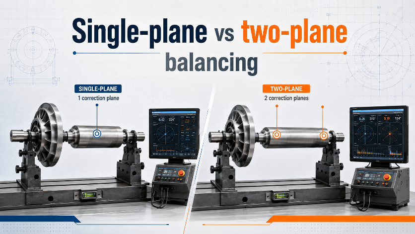
The choice between single-plane and two-plane balancing is not just a machine setting. It reflects the way unbalance is distributed along the rotor axis.
Single-plane balancing
Single-plane balancing corrects the resultant unbalance in one axial plane. It is most suitable for rotors that behave approximately like thin discs, where axial separation of the unbalance distribution produces little significant couple effect at the operating condition.
Typical examples can include narrow pulleys, thin fan wheels and other disc-like components, provided their geometry and speed make one-plane correction technically adequate.
Two-plane balancing
Two-plane balancing uses two separated correction planes. This allows correction of both the resultant static unbalance and the couple component caused by unequal unbalance distribution along the rotor length.
Longer fan rotors, drums, rollers, shaft assemblies and wide impellers commonly require two-plane balancing because their axial mass distribution cannot be represented accurately by one heavy spot.
What is couple unbalance?
Imagine equal unbalance masses at opposite ends of a rotor, positioned 180° apart. Their centrifugal forces can cancel as a net force through the centre, so the rotor may not show a simple static heavy spot. But the separated forces create a rotating moment or couple. When the rotor spins, that couple can produce vibration at the supports.
A rotor can be statically balanced and still need two-plane correction
Static balance means the centre of mass is on the rotational axis in a way that removes the tendency for the rotor to roll to a heavy spot under gravity. It does not prove that the axial distribution of mass is free from a couple. Dynamic measurement is required to detect that condition reliably.
Why simple length-to-diameter rules are not enough
Rules of thumb based on rotor width or L/D ratio can be useful for screening, but they are not universal. Rotor speed, axial mass distribution, bearing span, correction-plane spacing and sensitivity to couple unbalance all matter. ISO 21940-11 addresses the necessary number of correction planes as part of the balancing procedure for rigid rotors.
Practical workshop decision
- If the rotor is narrow and disc-like, one plane may be sufficient.
- If the rotor has substantial axial length or separated mass features, expect two planes.
- If one-plane correction reduces one support but leaves a strong opposite-end response, couple unbalance may be present.
- If the customer specifies two correction planes, do not downgrade to one plane simply because the machine can obtain a low reading at one sensor.
Correction plane spacing matters
The farther apart the two correction planes are, the more effectively a given pair of correction masses can generate a balancing couple. If both correction planes are very close together, large masses may be needed to correct a couple component. Rotor design and accessible correction locations therefore affect how practical a tolerance is.
Reporting
A useful balance report should state whether the rotor was balanced in one or two planes, identify the correction planes and record the final residual unbalance or agreed acceptance result. This avoids the ambiguous statement “balanced” without telling the next engineer what was actually done.
See also Static balancing vs dynamic balancing.